
Introduction
The world of drone piloting demands reliable, customizable controls that can operate in challenging environments. While many commercial options exist, they often come with limitations—outdated software, limited brightness for outdoor use, or restricted operating systems. Building your own custom remote controller offers a solution, allowing you to tailor every component to your specific needs.
In a recent Drone Software meetup, Godfrey Nolan, President of RIIS LLC, showed off a project to address the limitations of commercial controllers and to offer drone enthusiasts a path to creating their own NDAA-compliant solutions.
In this comprehensive guide, we’ll explore how to build a 3D-printed drone remote controller that runs QGroundControl on Windows 11 with an ultra-bright display for outdoor visibility. This project combines off-the-shelf components with custom 3D printing and simple electronics to create a professional-grade controller that puts you in complete command of your aerial operations. As usual, you can follow along with the video or the written tutorial below.
Understanding the Problem
This won’t just be any run-of-the-mill drone controller. To make it useful in the widest array of scenarios, it will need to meet these core requirements:

A super-bright touch screen (2,400 nits compared to typical 500 nits displays)
Windows 11 capability (with options for Linux or Android if desired)
3D-printable housing for complete customization
Analog joystick and button inputs for precise control
Potential for NDAA compliance for those needing regulatory compatibility

This will ensure it can operate in real-world conditions like bright outdoor lighting as well as for a range of clients in both the private and public spheres.
Project Overview
The project involves three core tasks: sourcing readily available off-the-shelf components, designing a custom joystick and button input system, and creating a 3D printable housing to integrate everything. This approach uses accessible modules and straightforward assembly techniques, making it manageable even for those with more software than hardware experience.
Task 1: Sourcing Components
The quality of the controller will begin and end with the quality of the components. To lighten the load we have also focused on sourcing complete and integrated components when possible.
The heart of the controller consists of several key components:
Intel NUC Mainboard

The Intel NUC (Next Unit of Computing) offers a compact yet powerful computing solution. These small form-factor PC boards are typically sold as complete mini-PCs but can be purchased as standalone boards. This makes it perfect for integration into custom projects.
The NUC provides multiple CPU options, various RAM configurations, and built-in Wi-Fi capabilities. While initially sourced from AliExpress, considerations about NDAA compliance led to investigating ASUS (a Taiwanese company) as a potentially compliant alternative.
Ultra-Bright Display

Perhaps the most critical component for outdoor drone operations is the display. Standard smartphone displays or laptop screens typically offer around 500 nits of brightness, making them nearly impossible to see clearly in direct sunlight.
The project uses a 7-inch LCD touch display offering an impressive 2,400 nits—approximately five times brighter than a typical smartphone. This display includes an HDMI input, USB power input, and touch output capability.
Importantly, displays don’t necessarily need to be NDAA compliant according to our initial research, offering more flexibility in sourcing this component, but if you are targeting NDAA, it doesn’t hurt to check with an attorney or specialized consultant.
Hall Effect Joysticks

For the precision control essential to drone operations, the project uses hall effect joysticks. These components use magnetic fields to detect position, offering greater durability and precision than traditional potentiometer-based joysticks. The ones we are utilizing are relatively cheap, but if you are looking for more comfort and nuanced control, premium options are available.
Tactile Buttons

Simple yet essential, tactile buttons provide the clickable feedback necessary for drone control. These components are inexpensive and readily available from electronics suppliers.
Arduino Pro Micro

The Arduino Pro Micro serves as the Human Interface Device (HID) for the controller in this build. It reads the analog inputs from the joysticks and digital inputs from the buttons, then presents them to the Windows 11 system as either a gamepad or mouse input.
This approach leverages extensive libraries already available for Arduino, simplifying the development process.
The Arduino Pro Micro does not meet the NDAA compliance standard, but an Adafruit ItsyBitsy nRF52840 can potentially be substituted in.
Additional Components
The project also requires:

A toggle switch to change between mouse and gamepad modes


Various connectors for internal wiring


Fasteners for assembling the 3D-printed housing
Bill of Materials
Part | Listed Price (USD) | Specs | Link | Notes |
Display | $175.77 | 2400 nit, 1080p, 7in. touch display | Select "Full Kit" | |
Single Board Computer | $239.00 | BLKNUC7I5DNBE, I5-7300U | Might need fan? Consider newer gen CPU | |
NUC AC Power supply | $18.99 | 19V 65W | ||
SSD storage | $19.00 | 128GB NVMe | Select "128GB" | |
RAM | $28.99 | 16GB DDR4 | Select 16GB (2x8GB) | |
WiFi card | $24.29 | AX210 | ||
WiFi antennas | $9.29 |
The approximate cost for all components totals a little over $500, though this figure will vary based on component availability and current tariffs. When in the prototyping phase, you may want to order double of almost everything. Especially if this is your first time, this will help because components will fail, you will break them, and sometimes, you just want to have a backup in case of an accident in the field. This redundancy can be particularly important when ordering from international suppliers with lengthy shipping times.
Task 2: Custom Joysticks and Button Integration
Head on over to our Github Repo for this tutorial, which contains the code, PCB files, and 3D design files for the controller. As stated above, we selected the Arduino Pro Micro as our HID. Our PCBs will be custom printed, so we aren’t constrained by other manufacturers’ design choices.
Custom PCB Design
To create a clean, reliable connection between components, the project uses custom-designed Printed Circuit Boards (PCBs) rather than point-to-point wiring. You can find the ones we designed for this project in the pcbs folder on the Github repo.

The design includes two PCBs:
A small left PCB for mounting the left analog stick
A larger right PCB that hosts the right analog stick, four buttons, the mode toggle switch, and the Arduino itself
The PCBs were designed using KiCad, an open-source electronic design automation suite. The process involved:
Creating the schematic to define electrical connections
Designing the physical board layout
Exporting the design files
Sending them to a PCB manufacturer
In our experience shipping cost exceeded the PCB manufacturing cost ($15), suggesting that finding local PCB manufacturers might be more economical for future iterations. Also, take note that if you are trying to remain NDAA compliant, you will want to make sure your external PCB manufacturer is manufacturing locally.
Connecting the Components to the HID

With components in hand, the next task involves integrating the joysticks and buttons with the Arduino and main system. This requires:
Programming the Arduino to act as an HID device
Connecting analog joysticks to analog inputs
Connecting buttons to digital inputs
Creating a toggle mechanism between mouse and gamepad modes
Ensuring proper communication with the main Windows 11 system

Arduino Code Implementation
In the repo we’ve included a gamepad.ino file.
The Arduino code handles several key functions:
Reading analog inputs from the joysticks
Reading digital inputs from the buttons
Processing input based on the current mode (mouse or gamepad)
Sending appropriate commands to the main system
The code includes several sections. At the top of the file you see the HID device configuration (Mouse.h, Joystick.h, etc.) then followed by a list of hardware mappings denoted by #define
This sets up the necessary libraries and defines which pins connect to which inputs. The code then includes functions for mapping analog values, utility functions for button states, and calibration routines.
Next, the setup() function prepares the controller hardware and communication interfaces. It configures pins for joysticks and buttons, sets joystick output ranges, loads previous calibration data from permanent memory, and initializes the necessary HID interfaces (Joystick, Mouse, and Keyboard) to communicate with the host computer.
Let’s move on to the main loop.
Our main loop function handles the core control flow of the gamepad controller by first checking for calibration triggers through joystick button presses, then determining the operating mode via the switch pin. In mouse mode, it processes the left joystick for cursor movement and the right joystick for scroll wheel functionality (with rate limiting to prevent excessive scrolling), maps physical buttons to mouse clicks, and sends the appropriate HID commands. In joystick mode, it converts analog joystick readings to HID joystick values using calibration data stored in EEPROM, maps all four physical buttons to their corresponding gamepad buttons, and sends the complete state to the host system, creating a dual-purpose controller that can seamlessly switch between navigation and gaming functions.

Okay, that seems like a lot, but when you think about it, all that is really happening is we are mapping each piece component piece and its inputs, and how it will behave in each mode. In Mouse Mode, we will be able to navigate menus in our OS and in QGroundControl, and then Gamepad Mode will enable us to use dual sticks to control our drone in flight.
Task 3: 3D Printable Housing
The final major task involves designing and printing a housing to contain all the components.
Initially inspired by the publicly available Steam Deck design files, the team ultimately created their own custom design better suited to their specific needs. You can feel free to utilize our .3mf file to print your own, or you can use the NucDeck by Dan McKenzie.

The housing was split into multiple parts (six in the first iteration) to fit on the available 220×220mm print bed. Future revisions aim to reduce this to just two parts as larger print beds become available.

The housing includes:
Mounting points for the joysticks and buttons
Space for the display
An enclosure for the NUC mainboard
Cable routing channels
Fastener locations
Assembly Process
With all components ready, the assembly process follows these steps:
Circuit Board Assembly: The components are soldered to the PCBs, which are then connected together and fastened to the left and right 3D-printed grips.

Controller Face Assembly: The joystick rings and buttons are placed into the controller faces. The joystick rings (orange circles) are glued into the frame, while the switch and buttons fit loosely into place.


Grip and Controller Assembly: The grips and controller pieces are fastened together using screws. Nolan recommends using fasteners specifically designed for 3D-printed parts: “I like the fasteners that you can use in 3D printed… the ones that you indent into the plastic seem to work really well for us.”


Display Mounting: The display is mounted to the front of the controller with fastener points shown in red on the design. HDMI and USB-C ribbon cables connect to the display for video output and power.


NUC Installation: The NUC board is installed into the back frame and secured with four screws in the corners


Final Connections: At the front of the device, the HDMI ribbon cable connects to the display. At the rear, the two USB ribbon cables connect for the display board power, touch screen input, and Arduino interface.


And once those are all connected, this is what your device should look like:

System Setup
Once the hardware assembly is complete, the system requires several setup steps:
Power Supply: The current design uses a 19-volt external power supply for the NUC. Future revisions plan to incorporate internal batteries.
Windows 11 Installation: Standard Windows 11 installation via USB.
Driver Installation: Intel drivers for the NUC need to be installed.
WiFi Setup: If WiFi connectivity is desired, an antenna must be connected to the WiFi card.
HID Recognition: Due to the standardized HID protocol, no additional drivers should be needed for the Arduino to be recognized as a mouse/gamepad by Windows.
QGroundControl Installation: The ground control software is installed normally.
Joystick Calibration: The joysticks need to be calibrated through Windows’ game controller settings.
With these steps completed, the custom controller is ready to interface with drones. A telemetry radio (not integrated in the current design but planned for future versions) connects to the controller to communicate with the drone.
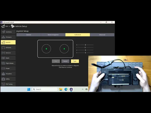
QGroundControl Calibration
We had screen issues at the last moment, so we hooked up a phone for the display for this test.
After assembling your controller and setting up the hardware, you'll need to calibrate it within QGroundControl (QGC) for optimal drone control. In QGC connect to the drone and then navigate to Vehicle Setup>Joystick>Button Assignment. Here you’ll want to make sure all your buttons trigger correctly. Then head over to the Calibration and first make sure you are seeing input feedback from the Joysticks, then hit the Start button to initiate the calibration process. Now you should be able to control your drone via QGC and the RC.
Final Steps and Field Testing

You’ll want to calibrate the brightness of the display for outdoor use. This will vary from display to display, but should be intuitive.
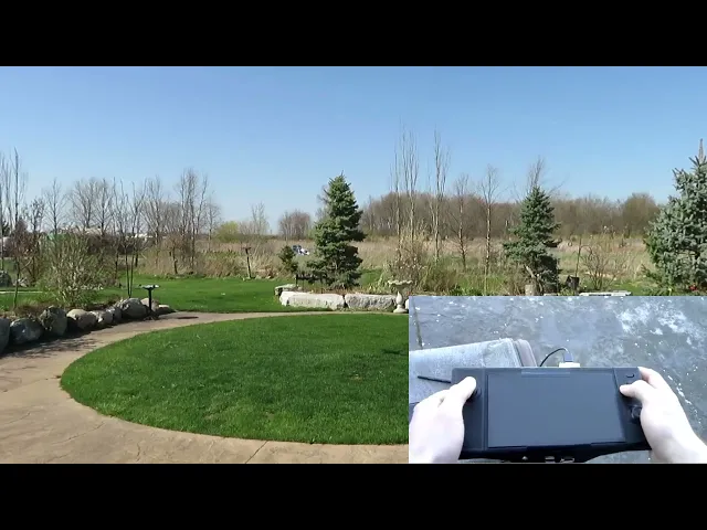
Now you can take your drone out to the field, connect to it via QGC, and give it a whirl. Since you are testing a custom controller, make sure to leave plenty of room (maybe a little more than normal) between you and the drone and that your test area is clear of bystanders.
Future Improvements
As with any project, there are several potential improvements for future iterations:
Hardware Enhancements
Internal Battery: Replacing the external power supply with internal batteries would make the controller fully portable. This would require careful consideration of battery capacity, weight distribution, and thermal management.
Integrated Telemetry Radio: Building in a telemetry radio would eliminate the need for an external device, streamlining the setup process and reducing the number of components to manage in the field.
Improved Button Layout: Additional buttons with a more ergonomic layout could enhance control capabilities. This would require modifications to both the 3D housing design and the Arduino programming.
Smaller NUC Board: Using a more compact computing solution could reduce the overall size and weight of the controller while maintaining performance.
Larger Print Bed: Access to a larger 3D printer bed would allow the housing to be printed in fewer pieces, improving structural integrity and reducing assembly time.
NDAA Compliance Considerations
When building your custom drone controller, NDAA compliance requires careful component selection. The flight controller (like PX4 Blue Cube), radio systems (Microhard or Doodle Labs), and data storage (SSD) must come from approved sources.
While displays aren't typically classified as "critical components" under NDAA restrictions, other electronic components require scrutiny.
Using an ASUS NUC motherboard offers a potential compliance pathway as ASUS is a Taiwanese-based. Standard cables generally don't raise compliance concerns, but components like the display controller and Arduino would need replacement with in-house designs or NDAA-compliant alternatives.
For camera and gimbal systems, approved options like Gremsys provide compliant solutions. Remember that NDAA compliance is essential for government contracts and certain commercial applications, so consulting with a compliance expert during your build process is highly recommended.
If you’re targeting NDAA compliance for commercial reasons, seek a specialist to verify your research before committing to your final design.
Conclusion
You've successfully created a professional-grade drone controller that outperforms some commercially available alternatives. Your custom-built remote now features an ultra-bright display for perfect visibility in any lighting condition, precision hall-effect joysticks for accurate control, and a powerful Windows 11 brain that can run any ground control software you need. More importantly, you've gained invaluable knowledge about electronics integration, 3D design, and embedded systems that will serve you well in future projects. We can't wait to see how you'll adapt this design to suit your unique requirements and what amazing aerial projects you'll tackle with your new custom controller.
